Setting Up Sensors - Gazebo
In this guide, we will discuss the importance of the sensors in navigating a robot safely and how to set up the sensors with Nav2. In the first half of this tutorial, we will take a brief look at commonly used sensors and common sensor messages in Nav2. Next, we will add a basic sensor setup on our previously built simulated robot, sam_bot. Lastly, we will then verify the simulated sensor messages of sam_bot by visualizing them in RViz.
Once sensors have been set up on a robot, their readings can be used in mapping, localization, and perception tasks. In the second half of this guide, we will first discuss how mapping and localization use the sensor data. Then, we will also take a look at one of Nav2’s packages, nav2_costmap_2d, which generates costmaps that will eventually be used in Nav2 path planning. We will set up basic configuration parameters for this package so it properly takes in sensor information from sam_bot. Lastly, we visualize a generated costmaps in RViz to verify its received data.
Sensor Introduction
Mobile robots are equipped with a multitude of sensors that allow them to see and perceive their environment. These sensors obtain information which can be used to build and maintain the map of the environment, to localize the robot on the map, and to see the obstacles in the environment. These tasks are essential to be able to safely and efficiently navigate a robot through a dynamic environment.
Examples of commonly used sensors are lidar, radar, RGB camera, depth camera, IMU, and GPS. To standardize the message formats of these sensors and allow for easier interoperation between vendors, ROS provides the sensor_msgs package that defines the common sensor interfaces. This also allows users to use any sensor vendor as long as it follows the standard format in sensor_msgs. In the next subsection, we introduce some of commonly used messages in navigation, namely the sensor_msgs/LaserScan, sensor_msgs/PointCloud2, sensor_msgs/Range, and sensor_msgs/Image.
Aside from the sensor_msgs package, there are also the radar_msgs and vision_msgs standard interfaces you should be aware of. The radar_msgs defines the messages for radar-specific sensors while the vision_msgs package defines the messages used in computer vision such as object detection, segmentation, and other machine learning models. Messages supported by this package are vision_msgs/Classification2D, vision_msgs/Classification3D, vision_msgs/Detection2D, and vision_msgs/Detection3D, to name a few.
See also
For more information, see the API documentation of sensor_msgs, radar_msgs, and vision_msgs.
Your physical robot’s sensors probably have ROS drivers written for them (e.g. a ROS node that connects to the sensors, populates data into messages, and publishes them for your robot to use) that follow the standard interface in the sensor_msgs package. The sensor_msgs package makes it easy for you to use many different sensors from different manufacturers. General software packages like Nav2 can then read these standardized messages and perform tasks independent of the sensor hardware. On simulated robots such as sam_bot, Gazebo has sensor plugins which also publish their information following the sensor_msgs package.
Common Sensor Messages
In this subsection, we discuss some of the common types of sensor_msgs you might encounter when setting up Nav2. We will provide a brief description for each sensor, an image of it being simulated in Gazebo and the corresponding visualization of the sensor readings in RViz.
Note
There are other types of sensor_msgs aside from the ones listed below. The complete list of messages and their definitions can be found in the sensor_msgs documentation.
sensor_msgs/LaserScan
This message represents a single scan from a planar laser range-finder. This message is used in slam_toolbox and nav2_amcl for localization and mapping, or in nav2_costmap_2d for perception.
sensor_msgs/PointCloud2
This message holds a collection of 3D points, plus optional additional information about each point. This can be from a 3D lidar, a 2D lidar, a depth camera or more.
sensor_msgs/Range
This is a single range reading from an active ranger that emits energy and reports one range reading that is valid along an arc at the distance measured. A sonar, IR sensor, or 1D range finder are examples of sensors that use this message.
sensor_msgs/Image
This represents the sensor readings from RGB or depth camera, corresponding to RGB or range values.
Simulating Sensors using Gazebo
To give you a better grasp of how to set up sensors on a simulated robot, we will build up on our previous tutorials and attach sensors to our simulated robot sam_bot. Similar to the previous tutorial where we used Gazebo plugins to add odometry sensors to sam_bot, we will be using the Gazebo plugins to simulate a lidar sensor and a depth camera on sam_bot. If you are working with a real robot, most of these steps are still required for setting up your URDF frames and it will not hurt to also add in the gazebo plugins for later use.
To be able to follow the rest of this section, make sure that you have properly installed Gazebo. You can follow the instructions at the Setup and Prerequisites of the previous tutorial to setup Gazebo.
Adding Gazebo Plugins to a URDF or SDF
Let us first add a lidar sensor to sam_bot. In your URDF paste the following lines before the </robot> tag to just add the lidar’s link and joint.
<link name="lidar_link">
  <inertial>
    <origin xyz="0 0 0" rpy="0 0 0"/>
    <mass value="0.125"/>
    <inertia ixx="0.001" ixy="0" ixz="0" iyy="0.001" iyz="0" izz="0.001" />
  </inertial>

  <collision>
    <origin xyz="0 0 0" rpy="0 0 0"/>
    <geometry>
      <cylinder radius="0.0508" length="0.055"/>
    </geometry>
  </collision>

  <visual>
    <origin xyz="0 0 0" rpy="0 0 0"/>
    <geometry>
      <cylinder radius="0.0508" length="0.055"/>
    </geometry>
  </visual>
</link>

<joint name="lidar_joint" type="fixed">
  <parent link="base_link"/>
  <child link="lidar_link"/>
  <origin xyz="0 0 0.12" rpy="0 0 0"/>
</joint>
In your SDF add the below before the </model> line to add the lidar’s link, joint, and Gazebo specific sensor information:
<joint name="lidar_joint" type="fixed">
  <parent>base_link</parent>
  <child>lidar_link</child>
  <pose relative_to="base_link">0.0 0.0 0.12 0 0 0</pose>
</joint>

<link name='lidar_link'>
  <pose relative_to="lidar_joint"/>
  <visual name="lidar_link_visual">
    <geometry>
      <cylinder>
        <radius>0.0508</radius>
        <length>0.055</length>
      </cylinder>
    </geometry>
  </visual>

  <collision name="lidar_link_collision">
    <geometry>
      <cylinder>
        <radius>0.0508</radius>
        <length>0.055</length>
      </cylinder>
    </geometry>
  </collision>

  <xacro:cylinder_inertia m="0.125" r="0.0508" h="0.055"/>

  <sensor name="lidar" type="gpu_lidar">
    <always_on>true</always_on>
    <visualize>true</visualize>
    <update_rate>5</update_rate>
    <topic>scan</topic>
    <gz_frame_id>lidar_link</gz_frame_id>
    <lidar>
      <scan>
        <horizontal>
          <samples>360</samples>
          <resolution>1.000000</resolution>
          <min_angle>0.000000</min_angle>
          <max_angle>6.280000</max_angle>
        </horizontal>
      </scan>
      <range>
        <min>0.120000</min>
        <max>3.5</max>
        <resolution>0.015000</resolution>
      </range>
      <noise>
        <type>gaussian</type>
        <mean>0.0</mean>
        <stddev>0.01</stddev>
      </noise>
    </lidar>
  </sensor>
</link>
In the code snippet above we set the sensor values of lidar_link to the simulated lidar’s scan and range properties and set /scan as the topic to which it will publish the sensor_msgs/LaserScan messages.
Next, let us add a depth camera to sam_bot. In your URDF paste the following lines after the </joint> tag of the lidar sensor to just add the camera’s link and joint.
<link name="camera_link">
  <visual>
    <origin xyz="0 0 0" rpy="0 0 0"/>
    <geometry>
      <box size="0.015 0.130 0.022"/>
    </geometry>
  </visual>

  <collision>
    <origin xyz="0 0 0" rpy="0 0 0"/>
    <geometry>
      <box size="0.015 0.130 0.022"/>
    </geometry>
  </collision>

  <inertial>
    <origin xyz="0 0 0" rpy="0 0 0"/>
    <mass value="0.035"/>
    <inertia ixx="0.001" ixy="0" ixz="0" iyy="0.001" iyz="0" izz="0.001" />
  </inertial>
</link>

<joint name="camera_joint" type="fixed">
  <parent link="base_link"/>
  <child link="camera_link"/>
  <origin xyz="0.215 0 0.05" rpy="0 0 0"/>
</joint>
In your SDF, paste the following lines after the </link> tag of the lidar sensor to add the camera’s link, joint, and Gazebo specific sensor information:
<joint name="camera_joint" type="fixed">
  <parent>base_link</parent>
  <child>camera_link</child>
  <pose relative_to="base_link">0.215 0 0.05 0 0 0</pose>
</joint>

<link name='camera_link'>
  <pose relative_to="camera_joint"/>
  <visual name="camera_link_visual">
    <geometry>
      <box><size>
        0.015 0.130 0.0222
      </size></box>
    </geometry>
  </visual>

  <collision name="camera_link_collision">
    <geometry>
      <box><size>
        0.015 0.130 0.0222
      </size></box>
    </geometry>
  </collision>

  <xacro:box_inertia m="0.035" w="0.015" d="0.130" h="0.0222"/>

  <sensor name="depth_camera" type="rgbd_camera">
    <always_on>true</always_on>
    <visualize>true</visualize>
    <update_rate>5.0</update_rate>
    <topic>depth_camera</topic>
    <gz_frame_id>camera_link</gz_frame_id>
    <camera>
      <horizontal_fov>1.047198</horizontal_fov>
      <image>
        <width>640</width>
        <height>480</height>
      </image>
      <clip>
        <near>0.05</near>
        <far>3</far>
      </clip>
    </camera>
    <baseline>0.2</baseline>
    <pointCloudCutoff>0.5</pointCloudCutoff>
    <pointCloudCutoffMax>3.0</pointCloudCutoffMax>
    <distortionK1>0</distortionK1>
    <distortionK2>0</distortionK2>
    <distortionK3>0</distortionK3>
    <distortionT1>0</distortionT1>
    <distortionT2>0</distortionT2>
    <CxPrime>0</CxPrime>
    <Cx>0</Cx>
    <Cy>0</Cy>
    <focalLength>0</focalLength>
    <hackBaseline>0</hackBaseline>
  </sensor>
</link>
In the code snippet above we set the sensor values of camera_link to the simulated depth camera’s properties and configure the sensor such that it will publish sensor_msgs/Image and sensor_msgs/PointCloud2 messages to /depth_camera/image_raw` and /depth_camera/points topics respectively.
Updating Bridge Config
We will also need to bridge the necessary sensor topics from Gazebo to ROS, add the following to your bridge_config.yaml:
- ros_topic_name: "/scan"
  gz_topic_name: "/scan"
  ros_type_name: "sensor_msgs/msg/LaserScan"
  gz_type_name: "gz.msgs.LaserScan"
  direction: GZ_TO_ROS

- ros_topic_name: "/scan/points"
  gz_topic_name: "/scan/points"
  ros_type_name: "sensor_msgs/msg/PointCloud2"
  gz_type_name: "gz.msgs.PointCloudPacked"
  direction: GZ_TO_ROS

- ros_topic_name: "/depth_camera/camera_info"
  gz_topic_name: "/depth_camera/camera_info"
  ros_type_name: "sensor_msgs/msg/CameraInfo"
  gz_type_name: "gz.msgs.CameraInfo"
  direction: GZ_TO_ROS

- ros_topic_name: "/depth_camera/points"
  gz_topic_name: "/depth_camera/points"
  ros_type_name: "sensor_msgs/msg/PointCloud2"
  gz_type_name: "gz.msgs.PointCloudPacked"
  direction: GZ_TO_ROS

 - ros_topic_name: "/depth_camera/image_raw"
   gz_topic_name: "/depth_camera/image"
   ros_type_name: "sensor_msgs/msg/Image"
   gz_type_name: "gz.msgs.Image"
   direction: GZ_TO_ROS
Build, Run and Verification
We can now build and run our project. Navigate to the root of the project and execute the following lines:
colcon build
. install/setup.bash
ros2 launch sam_bot_description display.launch.py
RViz and the Gazebo will then be launched with sam_bot present in both. In the Gazebo window, the world that we created should be launched and sam_bot should be spawned in that world. You should now be able to observe sam_bot with the 360 lidar sensor and the depth camera, as shown in the image below.
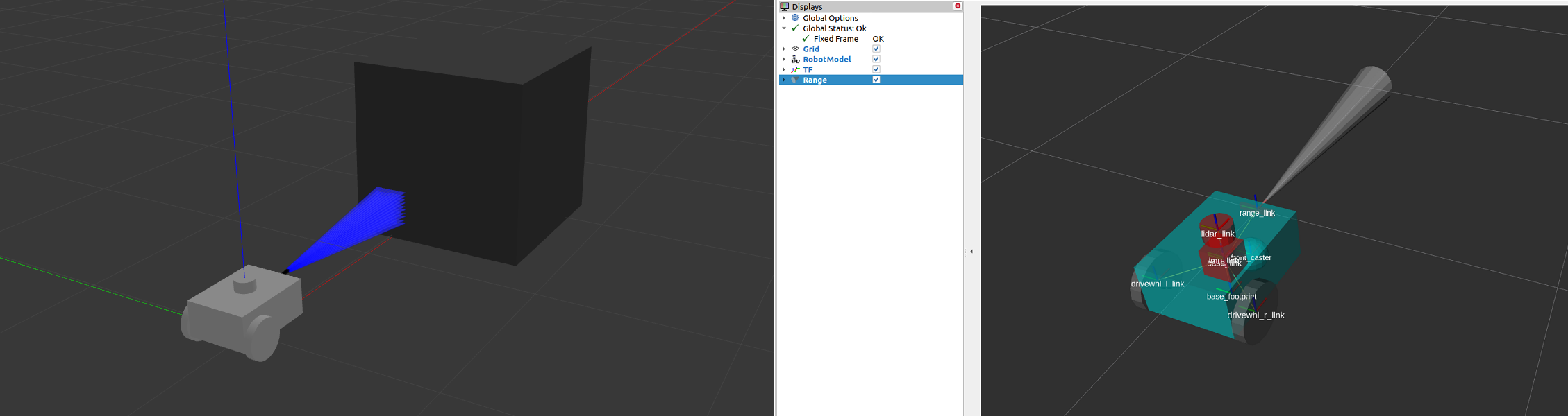
In the RViz window, we can verify if we have properly modeled our sensors and if the transforms of our newly added sensors are correct:

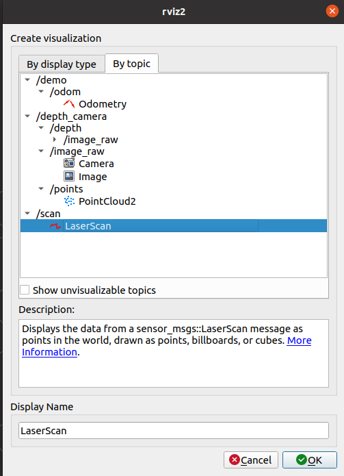
Lastly, we can also visualize the sensor readings in RViz. To visualize the sensor_msgs/LaserScan message published on /scan topic, click the add button at the bottom part of the RViz window. Then go to the By topic tab and select the LaserScan option under /scan, as shown below.
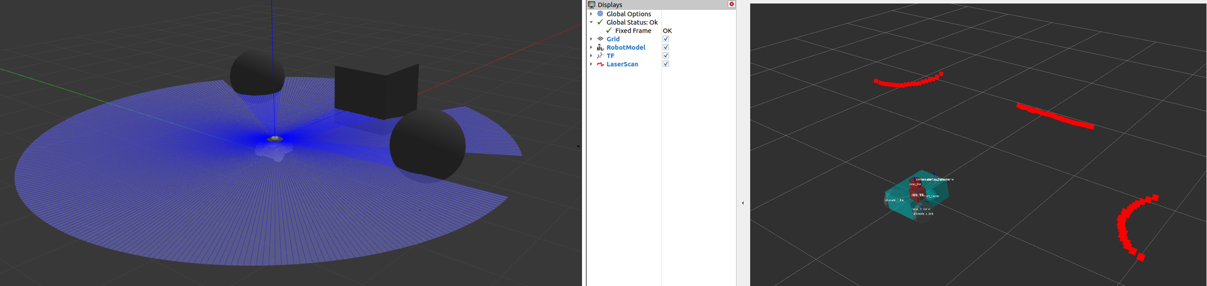
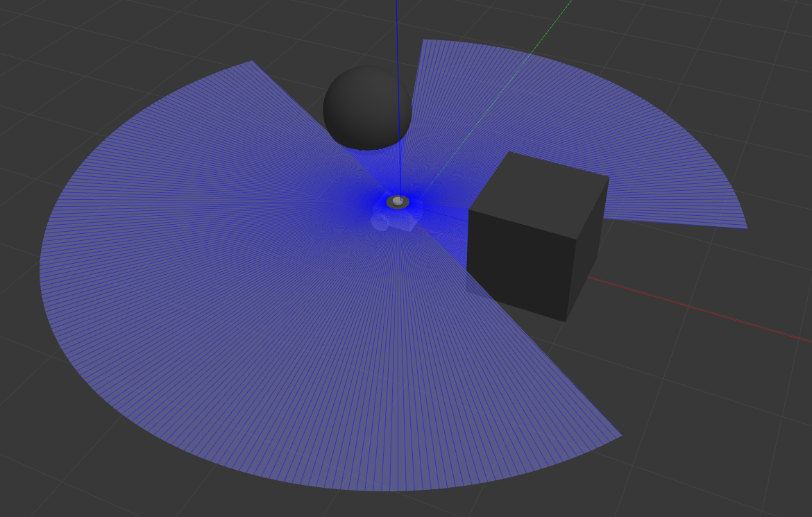
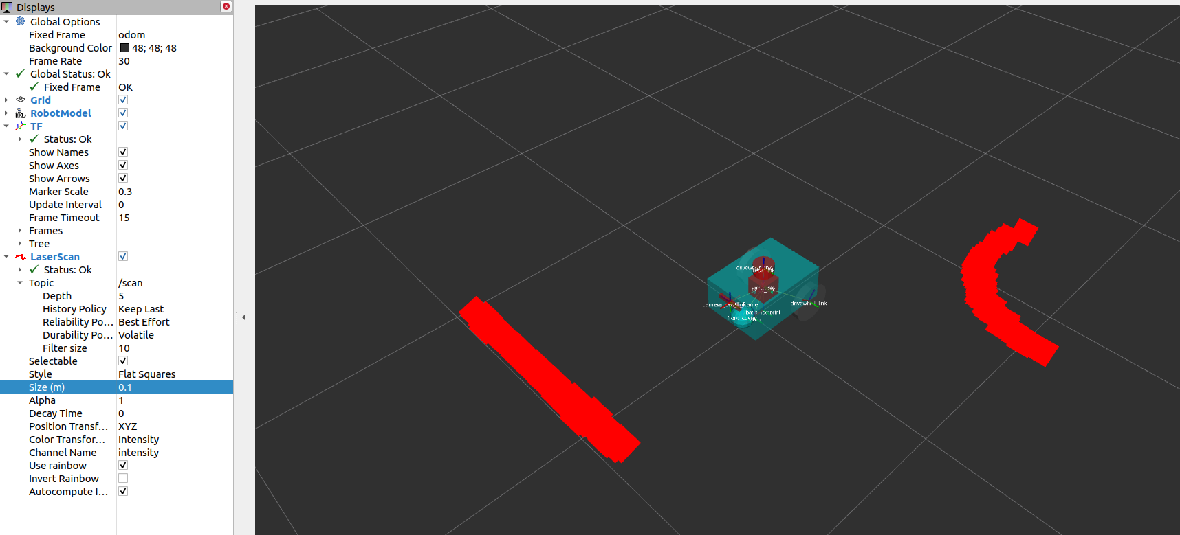
Next, set the Reliability Policy in RViz to Best Effort and set the size to 0.1 to see the points clearer. You should see the visualized LaserScan detection as shown below. This corresponds to the detected cube and sphere that we added to the Gazebo world.
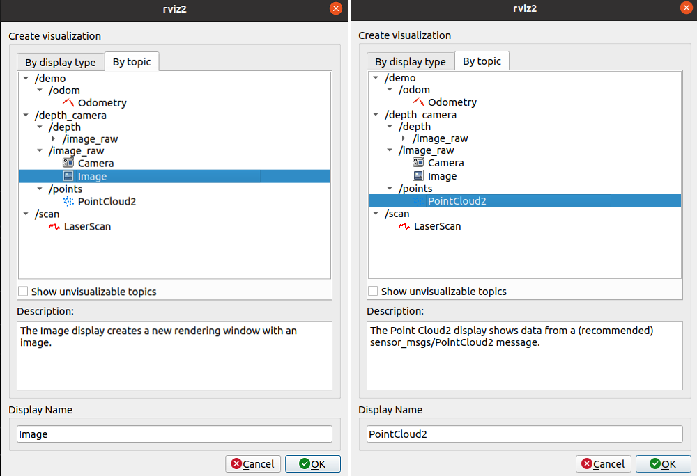
To visualize sensor_msgs/Image and sensor_msgs/PointCloud2, do the same for topics /depth_camera/image_raw and /depth_camera/points respectively:
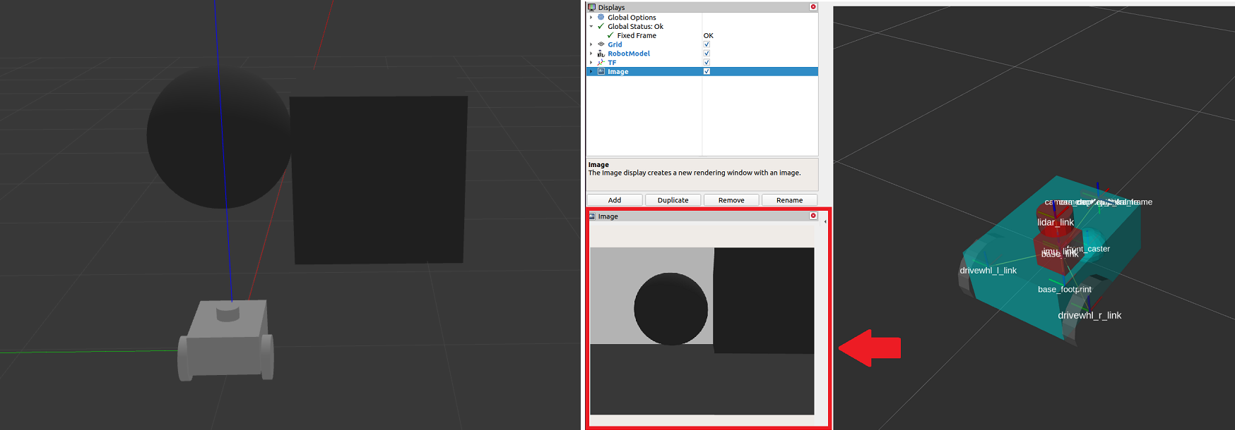
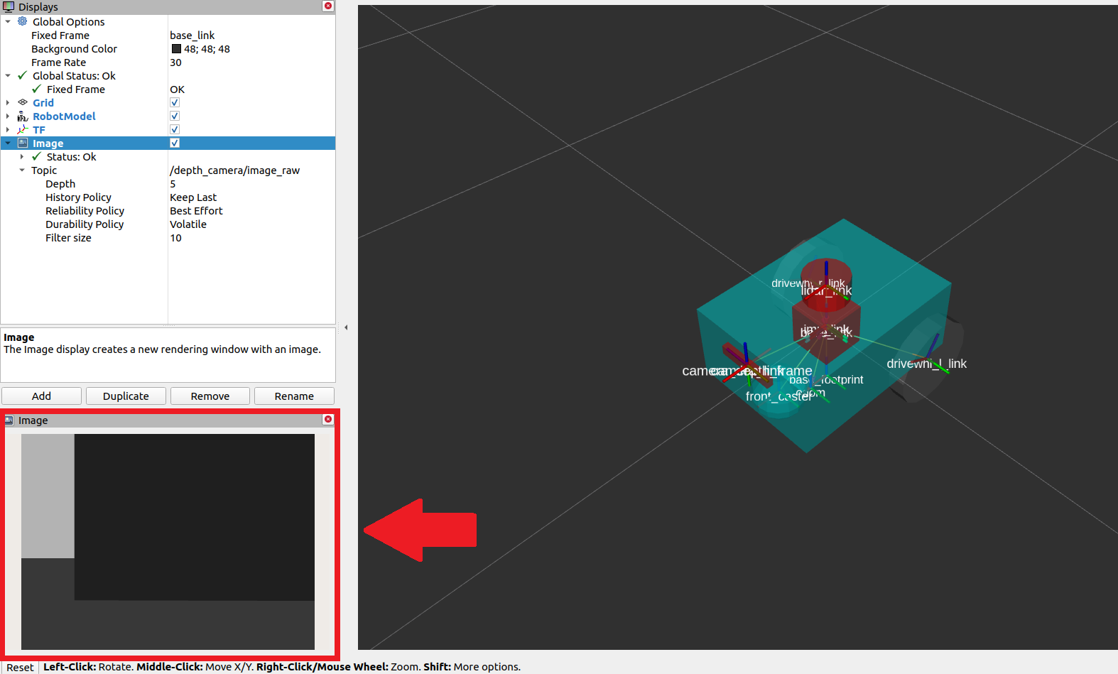
After adding the /depth_camera/image_raw topic in RViz, set the Reliability Policy in RViz to Best Effort. Then you should see the cube in the image window at the lower-left side of the RViz window, as shown below.
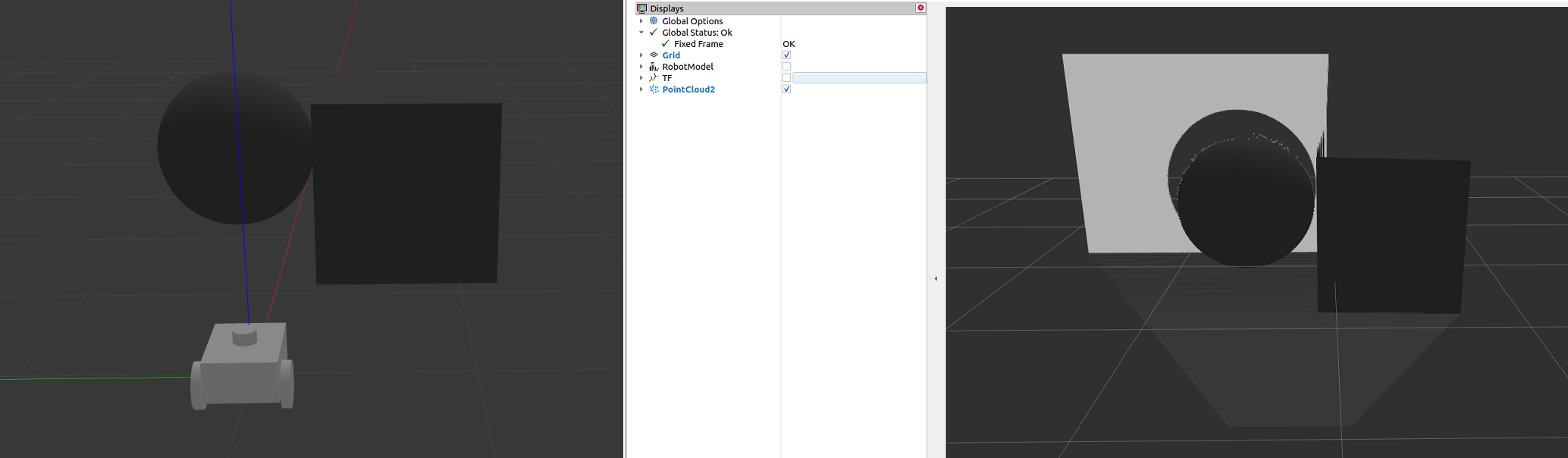
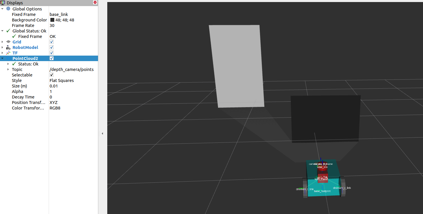
You should also see the sensor_msgs/PointCloud2, as shown below.
Conclusion
In this section of our robot setup guide, we had a discussion on the common types of sensor messages in Nav2 which standardize the message formats for different sensor vendors. We also discussed how to add sensors to a simulated robot using Gazebo and how to verify that the sensors are working correctly through RViz.