Setting Up Odometry - Gazebo
In this guide, we will be looking at how to integrate our robot’s odometry system with Nav2.
First we will provide a brief introduction on odometry, plus the necessary messages and transforms that need to be published for Nav2 to function correctly.
Next, we will show how to setup odometry with two different cases.
In the first case, we will show how to setup an odometry system for a robot with already available wheel encoders.
In the second case, we will build a demo that simulates a functioning odometry system on sam_bot (the robot that we built in the previous section) using Gazebo.
See also
The complete source code in this tutorial can be found in navigation2_tutorials repository under the sam_bot_description package. Note that the repository contains the full code after accomplishing all the tutorials in this guide.
Odometry Introduction
The odometry system provides a locally accurate estimate of a robot’s pose and velocity based on its motion. The odometry information can be obtained from various sources such as IMU, LIDAR, RADAR, VIO, and wheel encoders. One thing to note is that IMUs drift over time while wheel encoders drift over distance traveled, thus they are often used together to counter each other’s negative characteristics.
The odom frame and the transformation associated with it use a robot’s odometry system to publish localization information that is continuous but becomes less accurate over time or distance (depending on the sensor modalities and drift). In spite of this, the information can still be used by the robot to navigate its immediate vicinity (e.g collision avoidance). To obtain consistently accurate odometry information over time, the map frame provides globally accurate information that is used to correct the odom frame.
As discussed in the previous guides and in REP 105, the odom frame is connected to the rest of the system and Nav2 through the odom => base_link transform. This transform is published by a tf2 broadcaster or by frameworks such as robot_localization, which also provide additional functionalities. We will be talking more about robot_localization in a following section.
In addition to the required odom => base_link transform, Nav2 also requires the publishing of nav_msgs/Odometry message because this message provides the velocity information of the robot. In detail, the nav_msgs/Odometry message contains the following information:
# This represents estimates of position and velocity in free space.
# The pose in this message should be specified in the coordinate frame given by header.frame_id
# The twist in this message should be specified in the coordinate frame given by the child_frame_id

# Includes the frame id of the pose parent.
std_msgs/Header header

# Frame id the pose is pointing at. The twist is in this coordinate frame.
string child_frame_id

# Estimated pose that is typically relative to a fixed world frame.
geometry_msgs/PoseWithCovariance pose

# Estimated linear and angular velocity relative to child_frame_id.
geometry_msgs/TwistWithCovariance twist
This message tells us the estimates for the pose and velocity of the robot. The header message provides the timestamped data in a given coordinate frame. The pose message provides the position and orientation of the robot relative to the frame specified in header.frame_id. The twist message gives the linear and angular velocity relative to the frame defined in child_frame_id.
Setting Up Odometry on your Robot
Setting up the odometry system for Nav2 for your physical robot depends a lot on which odometry sensors are available with your robot. Due to the large number of configurations your robot may have, specific setup instructions will not be within the scope of this tutorial. Instead, we will provide some basic examples and useful resources to help you configure your robot for Nav2.
To start, we will use an example of a robot with wheel encoders as its odometry source. Note that wheel encoders are not required for Nav2 but it is common in most setups. The goal in setting up the odometry is to compute the odometry information and publish the nav_msgs/Odometry message and odom => base_link transform over ROS 2. To calculate this information, you will need to setup some code that will translate wheel encoder information into odometry information, similar to the snippet below:
linear = (right_wheel_est_vel + left_wheel_est_vel) / 2
angular = (right_wheel_est_vel - left_wheel_est_vel) / wheel_separation;
The right_wheel_est_vel and left_wheel_est_vel are the estimated velocities of the right and left wheels respectively, and the wheel separation is the distance between the wheels. The values of right_wheel_est_vel and left_wheel_est_vel can be obtained by simply getting the changes in the positions of the wheel joints over time. This information can then be used to publish the Nav2 requirements. A basic example on how to do this can be found in the Navigation documentation on odometry located here
An alternative to manually publishing this information that we recommend is through the ros2_control framework. The ros2_control framework contains various packages for real-time control of robots in ROS 2. For wheel encoders, ros2_control has a diff_drive_controller (differential drive controller) under the ros2_controller package. The diff_drive_controller takes in the geometry_msgs/Twist messages published on cmd_vel topic, computes odometry information, and publishes nav_msgs/Odometry messages on odom topic. Other packages that deal with different kind of sensors are also available in ros2_control.
See also
For more information, see the ros2_control documentation and the Github repository of diff_drive_controller.
For other types of sensors such as IMU, VIO, etc, their respective ROS drivers should have documentation on how publish the odometry information. Keep in mind that Nav2 requires the nav_msgs/Odometry message and odom => base_link transforms to be published and this should be your goal when setting up your odometry system.
Simulating an Odometry System using Gazebo
In this section, we will be using Gazebo to simulate the odometry system of sam_bot, the robot that we built in the previous section of this tutorial series. You may go through that guide first or grab the complete source here.
Note
If you are working on your own physical robot and have already set up your odometry sensors, you may opt to skip this section and head onto the next one where we fuse IMU and odometry messages to provide a smooth odom => base_link transformation.
As an overview for this section, we will first setup Gazebo and the necessary packages required to make it work with ROS 2. Next, we will be adding Gazebo plugins, which simulate an IMU sensor and a differential drive odometry system, in order to publish sensor_msgs/Imu and nav_msgs/Odometry messages respectively. Lastly, we will spawn sam_bot in a Gazebo environment and verify the published sensor_msgs/Imu and nav_msgs/Odometry messages over ROS 2.
Setup and Prerequisites
Gazebo is a 3D simulator that allows us to observe how our virtual robot will function in a simulated environment. To start using Gazebo with ROS 2, follow the installation instructions in the Gazebo Installation Documentation.
First, source your ROS 2 installation to set the environment variables:
source /opt/ros/<ros2-distro>/setup.bash
Then install the ROS-Gazebo integration package:
sudo apt install ros-$ROS_DISTRO-ros-gz
Adding Gazebo Plugins to a URDF/SDF
We will now add the IMU sensor and the differential drive plugins of Gazebo to our URDF/SDF. For an overview of the different sensors available in Gazebo, have a look at the Sensor Documentation.
A sensor must be attached to a link, thus we will create an imu_link to which the IMU sensor will be attached. This link will be referenced under the <gazebo> element if using URDF. Next, we will set /demo/imu as the topic to which the IMU will be publishing its information, and we will comply with REP145 by setting initialOrientationAsReference to false. We will also add some noise to the sensor configuration using Gazebo’s sensor noise model.
Now, we will set up our IMU sensor according to the description above.
Add the following lines before the </model> line in your robot SDF:
<joint name='imu_joint' type='fixed'>
  <parent>base_link</parent>
  <child>imu_link</child>
  <pose relative_to="base_link">0.0 0.0 0.01 0 0 0</pose>
</joint>

<link name='imu_link'>
  <pose relative_to="imu_joint"/>
  <visual name="imu_link_visual">
    <geometry>
      <box><size>
        0.1 0.1 0.1
      </size></box>
    </geometry>
  </visual>

  <collision name="imu_link_collision">
    <geometry>
      <box><size>
        0.1 0.1 0.1
      </size></box>
    </geometry>
  </collision>

  <xacro:box_inertia m="0.1" w="0.1" d="0.1" h="0.1"/>

  <sensor name="imu_sensor" type="imu">
    <always_on>true</always_on>
    <update_rate>100</update_rate>
    <visualize>true</visualize>
    <topic>demo/imu</topic>
    <gz_frame_id>imu_link</gz_frame_id>
    <imu>
      <angular_velocity>
        <x>
          <noise type="gaussian">
            <mean>0.0</mean>
            <stddev>2e-4</stddev>
            <bias_mean>0.0000075</bias_mean>
            <bias_stddev>0.0000008</bias_stddev>
          </noise>
        </x>
        <y>
          <noise type="gaussian">
            <mean>0.0</mean>
            <stddev>2e-4</stddev>
            <bias_mean>0.0000075</bias_mean>
            <bias_stddev>0.0000008</bias_stddev>
          </noise>
        </y>
        <z>
          <noise type="gaussian">
            <mean>0.0</mean>
            <stddev>2e-4</stddev>
            <bias_mean>0.0000075</bias_mean>
            <bias_stddev>0.0000008</bias_stddev>
          </noise>
        </z>
      </angular_velocity>
      <linear_acceleration>
        <x>
          <noise type="gaussian">
            <mean>0.0</mean>
            <stddev>1.7e-2</stddev>
            <bias_mean>0.1</bias_mean>
            <bias_stddev>0.001</bias_stddev>
          </noise>
        </x>
        <y>
          <noise type="gaussian">
            <mean>0.0</mean>
            <stddev>1.7e-2</stddev>
            <bias_mean>0.1</bias_mean>
            <bias_stddev>0.001</bias_stddev>
          </noise>
        </y>
        <z>
          <noise type="gaussian">
            <mean>0.0</mean>
            <stddev>1.7e-2</stddev>
            <bias_mean>0.1</bias_mean>
            <bias_stddev>0.001</bias_stddev>
          </noise>
        </z>
      </linear_acceleration>
    </imu>
  </sensor>
</link>
Now, let us add the DiffDrive plugin and the JointStatePublisher plugin. We will configure the plugins such that nav_msgs/Odometry messages are published on the /demo/odom topic, tf2_msgs/msg/TFMessage messages on the /tf topic, and the sensor_msgs/msg/JointState messages for the two wheels are published on /joint_states. The joints of the left and right wheels will be set to the wheel joints of sam_bot.
The wheel separation and wheel radius are set according to the values of the defined values of wheel_ygap and wheel_radius respectively.
Add the following lines after the </link> tag of the IMU sensor in your SDF:
<plugin filename="gz-sim-diff-drive-system" name="gz::sim::systems::DiffDrive">
  <!-- wheels -->
  <left_joint>drivewhl_l_joint</left_joint>
  <right_joint>drivewhl_r_joint</right_joint>

  <!-- kinematics -->
  <wheel_separation>0.4</wheel_separation>
  <wheel_radius>${wheel_radius}</wheel_radius>

  <!-- limits -->
  <max_linear_acceleration>0.1</max_linear_acceleration>

  <!-- input -->
  <topic>/demo/cmd_vel</topic>

  <!-- output -->
  <odom_topic>/demo/odom</odom_topic>
  <tf_topic>/tf</tf_topic>

  <frame_id>odom</frame_id>
  <child_frame_id>base_link</child_frame_id>
</plugin>

<plugin
  filename="gz-sim-joint-state-publisher-system"
  name="gz::sim::systems::JointStatePublisher">
  <topic>joint_states</topic>
</plugin>
Also set the friction of the caster wheel to near zero by modifying the caster link in your SDF as shown below. This is to keep things simple.
<link name="front_caster">
  <pose relative_to="caster_joint"/>

  <visual name="front_caster_visual">
    <geometry>
      <sphere>
        <radius>${(wheel_radius+wheel_zoff-(base_height/2))}</radius>
      </sphere>
    </geometry>
    <material>
      <ambient>0 1 1 1</ambient>
      <diffuse>0 1 1 1</diffuse>
    </material>
  </visual>

  <collision name="front_caster_collision">
    <geometry>
      <sphere>
        <radius>${(wheel_radius+wheel_zoff-(base_height/2))}</radius>
      </sphere>
    </geometry>
    <surface><friction><ode>
      <mu>0.001</mu>
      <mu2>0.001</mu2>
    </ode></friction></surface>
  </collision>

  <xacro:sphere_inertia m="0.5" r="${(wheel_radius+wheel_zoff-(base_height/2))}"/>
</link>
Creating ROS<->Gazebo Bridge
There is a bridge included in the ros_gz_bridge package which allows us to translate Gazebo topics into ROS topics and vice-versa. We need to launch the bridge with a configuration which tells it about what topics we want to bridge.
Now, create a file named bridge_config.yaml in the config directory of your package and add the following lines to it to define what topics we want to bridge between ROS and Gazebo:
---
- ros_topic_name: "/clock"
  gz_topic_name: "/clock"
  ros_type_name: "rosgraph_msgs/msg/Clock"
  gz_type_name: "gz.msgs.Clock"
  direction: GZ_TO_ROS

- ros_topic_name: "/demo/imu"
  gz_topic_name: "/demo/imu"
  ros_type_name: "sensor_msgs/msg/Imu"
  gz_type_name: "gz.msgs.IMU"
  direction: GZ_TO_ROS

# Topic published by DiffDrive plugin
- ros_topic_name: "/demo/odom"
  gz_topic_name: "/demo/odom"
  ros_type_name: "nav_msgs/msg/Odometry"
  gz_type_name: "gz.msgs.Odometry"
  direction: GZ_TO_ROS

# Topic published by JointStatePublisher plugin
- ros_topic_name: "/joint_states"
  gz_topic_name: "/joint_states"
  ros_type_name: "sensor_msgs/msg/JointState"
  gz_type_name: "gz.msgs.Model"
  direction: GZ_TO_ROS

# Topic subscribed to by DiffDrive plugin
- ros_topic_name: "/demo/cmd_vel"
  gz_topic_name: "/demo/cmd_vel"
  ros_type_name: "geometry_msgs/msg/TwistStamped"
  gz_type_name: "gz.msgs.Twist"
  direction: ROS_TO_GZ

- ros_topic_name: "/tf"
  gz_topic_name: "/tf"
  ros_type_name: "tf2_msgs/msg/TFMessage"
  gz_type_name: "gz.msgs.Pose_V"
  direction: GZ_TO_ROS
Finally, add the below variable to the launch file which we will use in the next section to tell the bridge where the config file is:
bridge_config_path = os.path.join(pkg_share, 'config', 'bridge_config.yaml')
Making a Gazebo world
Create a world directory in your package and add this code to a new file named my_world.sdf:
We also have to add the world directory to our CMakeLists.txt file. Open CMakeLists.txt and append the world directory inside the install(DIRECTORY…), as shown in the snippet below.
install(
  DIRECTORY src launch rviz config world
  DESTINATION share/${PROJECT_NAME}
)
Finally, add the below variable to the launch file which we will use in the next section to tell Gazebo where the world file is located:
world_path = os.path.join(pkg_share, 'world', 'my_world.sdf')
Launch and Build Files
We will now edit our launch file to spawn sam_bot in Gazebo. Since the JointStatePublisher plugin will now publish the joint_states, we can remove everything related to the joint state publisher by deleting the following lines inside the generate_launch_description():
joint_state_publisher_node = Node(
    package='joint_state_publisher',
    executable='joint_state_publisher',
    name='joint_state_publisher',
    parameters=[{'robot_description': Command(['xacro ', default_model_path])}],
    condition=UnlessCondition(LaunchConfiguration('gui'))
)
joint_state_publisher_gui_node = Node(
    package='joint_state_publisher_gui',
    executable='joint_state_publisher_gui',
    name='joint_state_publisher_gui',
    condition=IfCondition(LaunchConfiguration('gui'))
)
Remove the following from return LaunchDescription([]):
DeclareLaunchArgument(name='gui', default_value='True', description='Flag to enable joint_state_publisher_gui'),
joint_state_publisher_node,
joint_state_publisher_gui_node,
Next, open package.xml and delete the lines:
<exec_depend>joint_state_publisher</exec_depend>
<exec_depend>joint_state_publisher_gui</exec_depend>
Replace your import statements with the following lines.
We use RosGzBridge to start the bridge between ROS 2 and Gazebo and GzServer to start the Gazebo simulation.
We also import get_package_share_directory, ExecuteProcess, IncludeLaunchDescription and PythonLaunchDescriptionSource for additional changes in the launch file.
import os

from ament_index_python.packages import get_package_share_directory
from launch import LaunchDescription
from launch.actions import DeclareLaunchArgument, ExecuteProcess, IncludeLaunchDescription
from launch.launch_description_sources import PythonLaunchDescriptionSource
from launch.substitutions import Command, LaunchConfiguration
from launch_ros.actions import Node
from ros_gz_bridge.actions import RosGzBridge
from ros_gz_sim.actions import GzServer
Since we do not import FindPackageShare anymore, we use the function get_package_share_directory instead to find the package share directory.
Edit the variable definition of pkg_share:
pkg_share = get_package_share_directory('sam_bot_description')
Add this two variables, which are needed for starting the Gazebo world and spawning the robot:
ros_gz_sim_share = get_package_share_directory('ros_gz_sim')
gz_spawn_model_launch_source = os.path.join(ros_gz_sim_share, "launch", "gz_spawn_model.launch.py")
To make robot_state_publisher use_sim_time change it in the following way:
robot_state_publisher_node = Node(
    package='robot_state_publisher',
    executable='robot_state_publisher',
    parameters=[{'robot_description': Command(['xacro ', LaunchConfiguration('model')])}, {'use_sim_time': LaunchConfiguration('use_sim_time')}]
)
Also declare the use_sim_time argument in LaunchDescription([]) by adding the below line to it:
DeclareLaunchArgument(name='use_sim_time', default_value='True', description='Flag to enable use_sim_time'),
To launch Gazebo and spawn sam_bot in it, add the following after the rviz_node definition display.launch.py:
gz_server = GzServer(
    world_sdf_file=world_path,
    container_name='ros_gz_container',
    create_own_container='True',
    use_composition='True',
)
ros_gz_bridge = RosGzBridge(
    bridge_name='ros_gz_bridge',
    config_file=bridge_config_path,
    container_name='ros_gz_container',
    create_own_container='False',
    use_composition='True',
)
spawn_entity = IncludeLaunchDescription(
    PythonLaunchDescriptionSource(gz_spawn_model_launch_source),
    launch_arguments={
        'world': 'my_world',
        'topic': '/robot_description',
        'entity_name': 'sam_bot',
        'z': '0.65',
    }.items(),
)
Also add the following lines to LaunchDescription([]):
ExecuteProcess(cmd=['gz', 'sim', '-g'], output='screen'),
gz_server,
ros_gz_bridge,
spawn_entity,
Finally, add the below lines to your package.xml:
<exec_depend>ros_gz_bridge</exec_depend>
<exec_depend>ros_gz_sim</exec_depend>
At this point, your entire launch file should look like this:
import os

from ament_index_python.packages import get_package_share_directory
from launch import LaunchDescription
from launch.actions import DeclareLaunchArgument, ExecuteProcess, IncludeLaunchDescription
from launch.launch_description_sources import PythonLaunchDescriptionSource
from launch.substitutions import Command, LaunchConfiguration
from launch_ros.actions import Node
from ros_gz_bridge.actions import RosGzBridge
from ros_gz_sim.actions import GzServer

def generate_launch_description():
    pkg_share = get_package_share_directory('sam_bot_description')
    ros_gz_sim_share = get_package_share_directory('ros_gz_sim')
    gz_spawn_model_launch_source = os.path.join(ros_gz_sim_share, "launch", "gz_spawn_model.launch.py")
    default_model_path = os.path.join(pkg_share, 'src', 'description', 'sam_bot_description.sdf')
    default_rviz_config_path = os.path.join(pkg_share, 'rviz', 'config.rviz')
    world_path = os.path.join(pkg_share, 'world', 'my_world.sdf')
    bridge_config_path = os.path.join(pkg_share, 'config', 'bridge_config.yaml')

    robot_state_publisher_node = Node(
        package='robot_state_publisher',
        executable='robot_state_publisher',
        parameters=[{'robot_description': Command(['xacro ', LaunchConfiguration('model')])}, {'use_sim_time': LaunchConfiguration('use_sim_time')}]
    )
    rviz_node = Node(
        package='rviz2',
        executable='rviz2',
        name='rviz2',
        output='screen',
        arguments=['-d', LaunchConfiguration('rvizconfig')],
    )
    gz_server = GzServer(
        world_sdf_file=world_path,
        container_name='ros_gz_container',
        create_own_container='True',
        use_composition='True',
    )
    ros_gz_bridge = RosGzBridge(
        bridge_name='ros_gz_bridge',
        config_file=bridge_config_path,
        container_name='ros_gz_container',
        create_own_container='False',
        use_composition='True',
    )
    spawn_entity = IncludeLaunchDescription(
        PythonLaunchDescriptionSource(gz_spawn_model_launch_source),
        launch_arguments={
            'world': 'my_world',
            'topic': '/robot_description',
            'entity_name': 'sam_bot',
            'z': '0.65',
        }.items(),
    )

    return LaunchDescription([
        DeclareLaunchArgument(name='use_sim_time', default_value='True', description='Flag to enable use_sim_time'),
        DeclareLaunchArgument(name='model', default_value=default_model_path, description='Absolute path to robot model file'),
        DeclareLaunchArgument(name='rvizconfig', default_value=default_rviz_config_path, description='Absolute path to rviz config file'),
        ExecuteProcess(cmd=['gz', 'sim', '-g'], output='screen'),
        robot_state_publisher_node,
        rviz_node,
        gz_server,
        ros_gz_bridge,
        spawn_entity,
    ])
Build, Run and Verification
Let us run our package to check if the /demo/imu and /demo/odom topics are active in the system.
Navigate to the root of the project and execute the following lines:
colcon build
. install/setup.bash
ros2 launch sam_bot_description display.launch.py
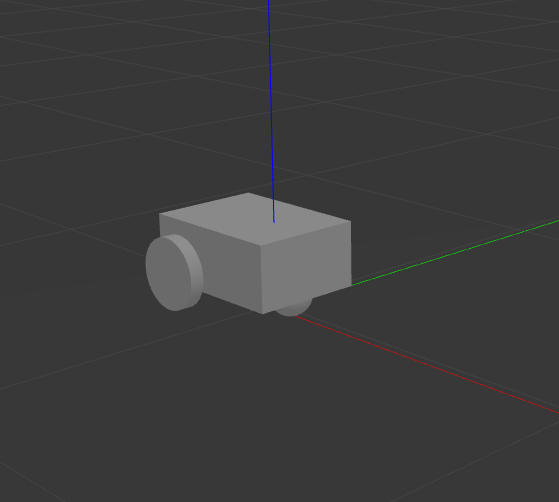
Gazebo should launch and you should see a 3D model of sam_bot:
To see the active topics in the system, open a new terminal and execute:
ros2 topic list
You should see the below topics in the list of topics:
/clock
/demo/cmd_vel
/demo/imu
/demo/odom
/joint_states
/tf
To see more information about the topics, execute:
ros2 topic info /topic
Now set the fixed frame in RViz to odom and execute the below command in order to move the robot around:
ros2 run teleop_twist_keyboard teleop_twist_keyboard --ros-args -p stamped:=true --remap cmd_vel:=/demo/cmd_vel
You should see the robot moving in both Gazebo and RViz.
Something to note here is that we are using TwistStamped messages here as those are now the standard in most packages for ROS2 Jazzy and newer. Some Nav2 nodes come with the enable_stamped_cmd_vel parameter which you can set to true. It defaults to true for any distro newer than ROS2 Jazzy.
Conclusion
In this guide, we have discussed the messages and transforms that are expected by Nav2 from the odometry system. We have seen how to set up an odometry system and how to verify the published messages.